Electronic projects |
|
|
|
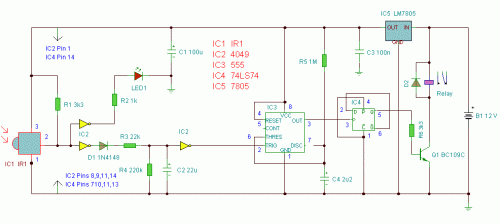
Infra Red SwitchDescription: Notes: Circuit Operation: The pulses are further buffered and contain "jaggered edges" as shown above. These edges are produced by the modulated IR data, which has to be removed. This is achieved using IC3, a 555 timer wired as a monostable, pulse duration R5, C4. These cleanly reconstructs a single clean pulse to activate the bistable latch. A D type flip flop, IC4 is configured as a bistable. The input is applied to the clock pin, the inverted output fed back to the data input and clear and preset lines are tied to ground. For every pulse the relay will operate and latch, the next pulse will turn off the relay and so on. Note that quick turn on and off of the relay is not possible. The output pulse is set at about 1.5 seconds and input delay by R3, C2 set at two seconds. Parts e-mail: anc@mitedu.freeserve.co.uk web site: http://www.zen22142.zen.co.uk |
 Audio (49) Audio (49) Power & high voltage (43) Power & high voltage (43) Radio (23) Radio (23) Light & LED (31) Light & LED (31) Tools & measurement (40) Tools & measurement (40) Telephone (18) Telephone (18) Automotive (10) Automotive (10) Microcontrollers (12) Microcontrollers (12) Sensors & control (47) Sensors & control (47) Timers & oscillators (40) Timers & oscillators (40) Miscellaneous (26) Miscellaneous (26)All subcategories light controlled temperature controlled moisture controlled sound controlled other Infa-Red Remote Control Infra Red Remote Control Extender Infra-red Level Detector Infrared Detector Infrared gate 2 Infrared Remote Control IR Remote Control Extender Circuit Light switch Light/Dark Detector Simple optical switch Doorbell for the Deaf High Quality Intercom Combinational Conjuring Trick POT-PLANT POWER Ultrasonic Dog Whistle Quiz Circuit LED Torch Insect Repellant Speaker Microphone Circuit Magic Wand Conjuring Trick. Led display digital Voltmeter 500W low cost 12V to 220V inverter Low pass filter - Subwoofer High And Low Voltage Cut Off With Time Delay Metal Detector 2N3055 Power Amplifier Basic UPS Power Supply 200W audio amplifier LED Torch 100W RMS Amplifier DIY Electronics Projects  Promote Your Page Too |

