Electronic projects |
|
|
|
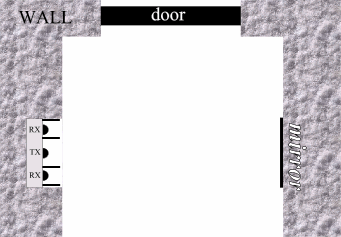
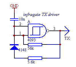
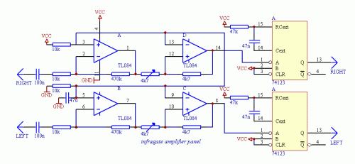
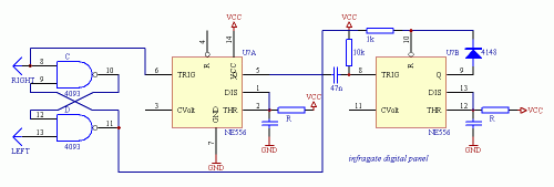
Infrared gate 2Description Schematics To start testing the infra LED panel, you wil need the infragate amplifier panel and the small transmiter driver. The TX driver will generate the digital signal for the LED driver on the LED panel. The digital signal is 1:10 on/off to achive good performance with lower power dissipation on the LEDs. Connect GND, VCC planes and LEFT, RIGHT wires of the LED panel with the amplifier panel, and drive the TX line from the TX driver. Now you are able to start testing and calibrating the analogue part of the circuit. If everything is ok, holding a mirror in front of the LED panel will reflect enough signal to overdrive the amplifier and you can check the output on the OPA 1, 7 pins with an oscilloscope. Taking the mirror farther on will result a weakening signal on the amplifier output. Set the orientation of the diodes to be able to get the maximum signal amplitude on the oscilloscope screen. This is the heaviest part of the work, don't deal too much with it until the complete circuit is not built. Just adjust a static state of the construction to give the maximum signal amplitude on the output when nothing is between the diodes and the mirror and give a small noise only when the line of sight is covered. If you are ready with it, you can adjust the schmitt triggers built of the other two OPA parts to generate TTL pulses when the analog signal is at its maximum and stay on the same DC level when the received signal is missing. It is also important to protect the receiver diodes from direct light as natural light will weaken the sensitivity of the diodes, and lamps will transform the 50/60 Hz modulation present in the line power. Small noise is not problem, but the received signal from the TX generator should be stronger to be able to detect it. After the ST adjustments, connect LEDs to the 74123's TTL outputs through proper value resistors. The 74123 here is used as a demodulator. If there is a periodic signal change on the input, the output will be high, while if there is no activity on the input for a given period of time, the output falls low. When you cover the line of sight of one receiver diode, the corresponding LED turns off. There should not be any flickering in the turning on/off, the output should immediately respond to the change without blinking. If still everything is correctly working at this point, the remaining digital circuit is the easy part of the work. The outputs of the previous circuit (LEFT, RIGHT) directly connect to the remaining part. The RS memory built from two NAND gates remembers the way of the last movement direction, so if someone is in or not. If you experience problems, connect another LED to pin 10 of the RS and check if this part does what it should. If there was any activity in the past minutes, the first timer is running, but it can only trigger the second timer part, if someone is still inside. The diode from the second timer output prevents resetting itself before the timing period is over in case of another movement. For a 1 minute timing (first timer) R=470k C=100u can be used, the second part would use R=1.5M C=470u for about a 15 minute timing (t=1.1RC). The output of the second timer (pin 9) can drive a relay activating the ventillator. e-mail: web site: http://www.electronics-lab.com |
 Audio (49) Audio (49) Power & high voltage (43) Power & high voltage (43) Radio (23) Radio (23) Light & LED (31) Light & LED (31) Tools & measurement (40) Tools & measurement (40) Telephone (18) Telephone (18) Automotive (10) Automotive (10) Microcontrollers (12) Microcontrollers (12) Sensors & control (47) Sensors & control (47) Timers & oscillators (40) Timers & oscillators (40) Miscellaneous (26) Miscellaneous (26)All subcategories light controlled temperature controlled moisture controlled sound controlled other Infa-Red Remote Control Infra Red Remote Control Extender Infra Red Switch Infra-red Level Detector Infrared Detector Infrared Remote Control IR Remote Control Extender Circuit Light switch Light/Dark Detector Simple optical switch Doorbell for the Deaf High Quality Intercom Combinational Conjuring Trick POT-PLANT POWER Ultrasonic Dog Whistle Quiz Circuit LED Torch Insect Repellant Speaker Microphone Circuit Magic Wand Conjuring Trick. Led display digital Voltmeter 500W low cost 12V to 220V inverter Low pass filter - Subwoofer High And Low Voltage Cut Off With Time Delay Metal Detector 2N3055 Power Amplifier Basic UPS Power Supply 200W audio amplifier LED Torch 100W RMS Amplifier DIY Electronics Projects  Promote Your Page Too |


