Electronic projects |
|
|
|
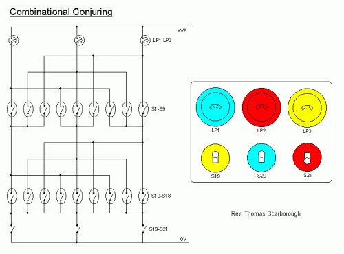
Combinational Conjuring TrickThe simple circuit of Fig.1 emulates a similar conjuring trick which sells for hundreds of Pounds. The trick seems to do the almost-impossible from an electronic point of view, let alone from the point of view of common sense. It consists of a bank of three on-off switches (S19-S21), which have three switch covers, each of a different colour. These switch a bank of three lightbulbs (LP1-LP3), each of a different colour. The colours of the lightbulbs correspond with the colours of the switch covers. Now comes the interesting part. The switch covers may be exchanged at will, but still they switch the lightbulbs of corresponding colour. Similarly, the lightbulbs may be exchanged at will, but still they respond to the switches of corresponding colour. On the surface of it, there would seem to be 64 possible connections between switches and lighbulbs, and no possible way that the conjurer can manipulate them all. Let us consider just one of the switch covers (S19). Three reed switches (S10-S12) are positioned beneath the cover, at positions N, E, and W, and each of these activates a different lightbulb. Any one of the three reed switches may be closed by a single magnet positioned strategically under the switch cover. Depending on the orientation of the switch cover, therefore, the switch will activate any one of the three reed switches, and thus the selected lightbulb. On discussing this with an accomplished magician, the author was told that this alone would be sufficient for the full effect described - reed switches S1-S9 may be omitted. Nevertheless, the lightbulbs may similarly be surrounded with three reed switches each, which are activated by the orientation of the circular base - a magnet being strategically positioned within it. These reed switches may thus reroute the power to the conjurer's selected lightbulb. There is just one caveat from an electronic point of view. Carefully consider the voltage and power ratings of the reed switches and on-off switches, to match these with the chosen lightbulbs. Failing this, your trick may demonstrate how none of the switches will activate none of the lightbulbs. e-mail: scarboro@iafrica.com web site: http://www.zen22142.zen.co.uk |
 Audio (49) Audio (49) Power & high voltage (43) Power & high voltage (43) Radio (23) Radio (23) Light & LED (31) Light & LED (31) Tools & measurement (40) Tools & measurement (40) Telephone (18) Telephone (18) Automotive (10) Automotive (10) Microcontrollers (12) Microcontrollers (12) Sensors & control (47) Sensors & control (47) Timers & oscillators (40) Timers & oscillators (40) Miscellaneous (26) Miscellaneous (26)All subcategories music & light LED applications other 220 Volts Flashing Lamps Battery-powered Night Lamp Black Light Brightness Control for small Lamps Courtesy Light Doorbell for the Deaf Instrument panel lamp dimmer control Magic Wand Conjuring Trick. Two-wire Lamp Flasher Doorbell for the Deaf High Quality Intercom Combinational Conjuring Trick POT-PLANT POWER Ultrasonic Dog Whistle Quiz Circuit LED Torch Insect Repellant Speaker Microphone Circuit Magic Wand Conjuring Trick. Led display digital Voltmeter 500W low cost 12V to 220V inverter Low pass filter - Subwoofer Metal Detector High And Low Voltage Cut Off With Time Delay Basic UPS Power Supply 2N3055 Power Amplifier 200W audio amplifier LED Torch 100W RMS Amplifier DIY Electronics Projects  Promote Your Page Too |
