Electronic projects


you are here: home page :: projects :: Timers & oscillators :: oscillators :: Reverse Bias Oscillator

Reverse Bias Oscillator

Circuit diagram
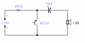
There are a number of npn transistors that will oscillate in the audio range when reverse biased. Minimum supply voltage is 7V for low power transistors such as BC109, BC238 and 2N2222A, it becomes 12V for medium power transistors such as BD139 and is 16V for power transistors as BUX22 and 2N6543. Current drain is 4mA at 9V and frequency of oscillation is 550Hz. The base is normally left open.

author: (C) G. Forrest Cook 1999
e-mail:
web site: http://www.electronics-lab.com
project categories:
folder Audio (49)
folder Power & high voltage (43)
folder Radio (23)
folder Light & LED (31)
folder Tools & measurement (40)
folder Telephone (18)
folder Automotive (10)
folder Microcontrollers (12)
folder Sensors & control (47)
folder Timers & oscillators (40)
folder Miscellaneous (26)

StumbleUpon button

Share this page
Bookmark and Share
project subcategories:
All subcategories
timer circuits
oscillators

similar projects:
1KHz Sinewave Generator
Adjustable High/Low Frequency Sine wave generator
Electronic Canary
Electronic Siren
Function Generator
Insect Repellant
Low-distortion Audio-range Oscillator
Mini Metronome
Precision Metronome and Pitch generator
Self-powered Sine to Square wave Converter

recently added projects:
Doorbell for the Deaf
High Quality Intercom
Combinational Conjuring Trick
POT-PLANT POWER
Ultrasonic Dog Whistle
Quiz Circuit
LED Torch
Insect Repellant
Speaker Microphone Circuit
Magic Wand Conjuring Trick.

most popular projects:
Led display digital Voltmeter
500W low cost 12V to 220V inverter
Low pass filter - Subwoofer
High And Low Voltage Cut Off With Time Delay
Metal Detector
2N3055 Power Amplifier
Basic UPS Power Supply
200W audio amplifier
LED Torch
100W RMS Amplifier


DIY Electronics Projects

Promote Your Page Too